Foreword
The blade is one of the main components of the steam turbine, and its steam section in particular determines the power generated by the steam turbine and directly affects the quality of the turbine product. With the continuous development of China's steam turbine industry, the design level of the blades is also constantly improving, mainly for the variable section twisted blades. The air path section line of the blade is a spatial coordinate data point, which requires high processing precision and is difficult to process. Harbin Turbine Co., Ltd. has jointly designed with the 3D company to improve the power generation efficiency and reduce heat consumption of steam turbines. The inlet and outlet steam fins of the blade steam path are relatively thin, and the top of the blade and the root of the blade have small round corners. From the processing to the inspection, a full line projection perspective is required, and the types vary, requiring a multi-axis CNC machine tool to process the equipment and process. The technical level is very demanding. Therefore, verifying the correctness of the NC machining program before CNC machining becomes a very important part of the NC machining process.
1 Characteristics of the Blade NC Steam Turbine, Blade Tip, and Root Radius NC Machining Procedure The blade airway profile is very complicated for spatial 3D design. First, we use B-Spline surfaces to fit the data points of the leaf shape. The given value points, then, the factors such as the width of the integrated processing band, the step length of the tool, the radius of the tool, etc., are interpolated and encrypted from the horizontal and vertical directions respectively, and the data points passed by the numerical control machining program are determined, thereby preparing the numerical control. Processing program. In the preparation of NC machining programs, in accordance with the principle of unity and reduction of the number of passes, the blade steam guide surface; the top of the blade, the fillet of the blade root, and the NC machining program of the inlet and outlet flanges are prepared together. There are tens of thousands of procedures for medium-length blades. The features of the program are: long program segments, large program coordinate point spans, tedious four-axis or five-axis program data, and many opportunities for errors. 2 Analysis of Common Mistakes in Blade NC Machining Programs As the design of blade air passages is becoming more and more complicated and the accuracy requirements are getting higher and higher, the NC machining programs are becoming more and more complex, and the probability of errors has increased. Generally, if the machining program is not properly prepared, the following problems may occur: Interference or collision between the tool and the workpiece; Excessive tool radius selection, incomplete machining of the part, large residual; Tool radius selection too small, cutting The efficiency is low; Machine feed speed or cooling status is not suitable; Processing plan is unreasonable, which affects processing efficiency; The control system of the machine tool does not accept the machining program; The shape or dimension of the part is wrong; The zero point selection is not appropriate and the tool point cannot be found. The appearance of these problems often causes a lot of troubles for the processing of the actual parts, such as reprogramming the machining program, grinding the parts after machining, repairing the parts or tooling, scrapping the parts, and delaying the product delivery. This will fundamentally weaken the reliability of CNC machining technology and affect its application. Therefore, the verification technology of NC machining program not only has important theoretical significance, but also has important practical significance. 3 Verification methods of commonly used numerical control machining programs Manual inspection methods The characteristics of manual inspection methods are more convenient and flexible. Usually the examiner reads the machining program, or uses the coordinate paper and some other drawing tools to check the tool path during machining and finds some errors. Due to the cumbersome and complicated process of blade steam path processing, the manual inspection method not only takes a lot of time, but also easily leads to errors again. Therefore, this method has gradually been eliminated. Test Processing The test processing method is a method of machining parts using leaf test pieces or other materials (mostly non-metallic materials). Because the test process intuitively and truly reflects the process, this method basically meets the need for program verification. Although the experimental processing method is an effective method for verifying the machining program, it also has many shortcomings, mainly including: Longer processing time; Inaccurate machining accuracy; Occupied the machine tool and affects the surrounding environment; Processing parameters cannot be verified; Although the use of experimental processing methods to verify the processing program has many shortcomings, but because it can more accurately reflect the entire process, and the overall level of China's blade CNC machining is still in the development stage, so this method is still used. Computer Simulation Verification With the rapid development of computer software and hardware, the use of computer simulation methods to verify the correctness of the blade surface NC machining program has been adopted. This method is mainly used to display the blade model, tool path, tool shape, etc. on the computer graphic display in the process of machining. This method is used to simulate the machining process of the part, check whether the tool position calculation is correct and whether the processing process occurs. Overcutting, whether the selected tool, the path of the knife, the way of entering and retracting the knife is reasonable, and whether the tool and the model face interference or collision. 4 Display Verification With the rapid development of computer simulation technology, there are many methods currently used for computer simulation verification of machining programs. Although the use of computer simulations validates that one-time investment costs are higher, it has been increasingly used because it can greatly reduce experimental processing costs and can bring long-term benefits. There are many methods for computer simulation verification. The most commonly used verification method for blade machining programs is the display trajectory verification method. That is, the wireframe of tool location data (spindle center coordinate and tool axis vector) is displayed, and whether the tool position trajectory is continuous is checked. The tool position calculation is correct. Then the tool position data is displayed together with the wire frame of the surface being machined, so as to judge whether the tool position path is correct or not, and whether the path of the tool path or the way of retracting the tool is reasonable. The basic idea is to remove all machining surfaces and related profiles from the surface modeling results, take out the tool path information from the tool position calculation results (tool location file), and then combine them to display, or in the selected tool. The tool model is placed on the site, and then the tool model is moved along the path of the tool to determine the location of the center of the tool on the tool path, the tool axis vector, the relative position of the tool and the machined surface, and whether the advance/retract mode is reasonable. Tool path trajectory display Verification of blade position path display verification method: When the blade's NC machining program is generated, the tool path trajectory is displayed on the graphic display to determine whether the tool position trajectory is correct. Among them, the information such as the feed speed, tool selection, and program line number in the NC machining program should be removed first, and only the verification information is displayed. Then, "inverse postprocessing" is performed on the tool path information, and after the NC machining program containing the tool path information is obtained, the tool path trace is drawn. This is illustrated by the four-axis NC machining program in which several rows of large blade inlet and outlet steam edges are machined: N0005X-25.875Y34.678Z34.78A26.68F200 N0006X-29.911Y34.789Z35.067A28.98 N0007X-34.023Y34.987Z35. 453A31.45 The three-coordinate values ​​X, Y, Z in this program are the values ​​after the rotary table rotates by the angle A. If the position coordinate of the tool is to be machined, the following “reverse post-processing†calculation should be performed. x1=x Y1=ycos(-A)+zsin(-A) z1=-ysin(-A)+zcos(-A) By calculating the (x1,y1,z1) is the coordinates of the tool location, this tool location can be used File plotting tool path. Tool path display verification principle:

Fig.1 Part of the tool path of the inner arc of the machining blade

Fig. 2 shows the combination of the blade inner arc surface and the tool path
Whether the tool path is continuous; whether the tool position is reasonable; whether the tool path is connected smoothly; whether the tool path intersects; whether the idle path is necessary; whether the tool axis vector has a sudden change; whether the tool path connection at the bump point is reasonable; Whether the cutter position trajectory during the surface machining is reasonable; whether the cutting direction matches the surface modeling. It can be seen from Figure 1 that the tool path trajectory is smooth, and the connection between each two tool paths is very reasonable. This is just one of them. The combined method of machining surface and tool path trajectory shows the basic method of verifying and combining the display verification: the tool path and the wire frame of the machining surface are displayed on the graphic display at the same time, so as to judge whether the tool position path is correct, and whether the tool path and advance and retreat mode are reasonable . Judgment principle of combined display verification method: whether the relative position of the tool path and the machining surface is reasonable; whether the offset direction of the tool path conforms to the actual requirements; whether there is interference between the tool and the machining surface; whether the advance and retract tool position and mode are reasonable from Fig. 2 shows that the tool advances in the direction of the arc-fitting surface of the blade, and the distance between the tool path and the machined surface is basically the same, and the tooling method is reasonable. In summary, the display verification method is a method suitable for verifying the tool path locus of the blade surface, in particular, the tip of the blade and the root of the blade. It is intuitive, easy to implement, and especially rotates from three coordinates on a computer monitor. Directional observations are more accurate.
Foam Roller

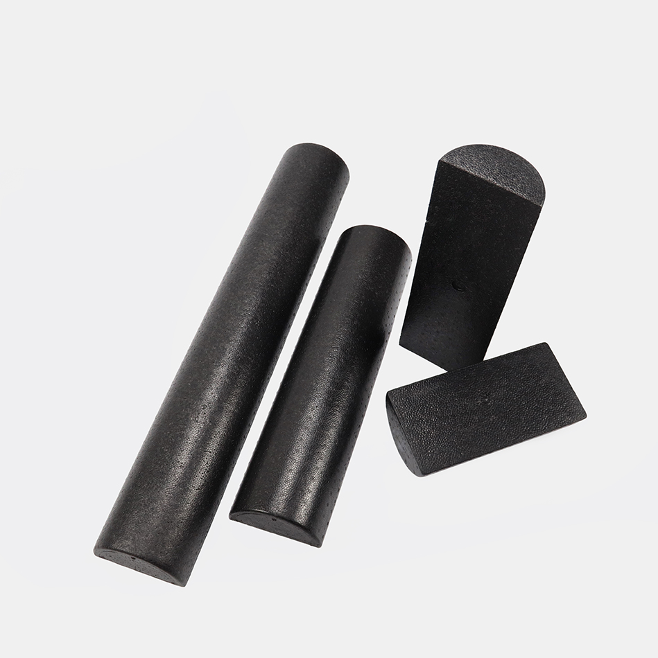
foam rollers are ideal for balance, strengthening, flexibility, and rehab exercises,and essential running tools
4 Sizes Available – 36 Inch, 24 Inch, 18 Inch, 12 Inch.
Our High-density Round Foam Roller 36" (90cm)stood out from the EPP pack as the best basic roller, proving you don`t have to spend a lot to get relief.
Half round foam rollers are used for leg and foot stretches, and to massage the arches of the feet to relieve the symptoms of plantar fascilites
Foam Roller,High Density Foam Rollers,Epp Foam Roller,half round foam rollers
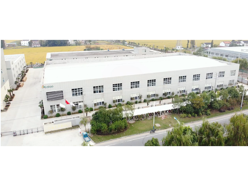
Jiangsu Laiao Material Technology Co., Ltd. , https://www.jiangsulaiao.com


