Abstract : In view of the current status of liquid level telemetering system in maritime applications, an intelligent liquid level telemetry system is developed based on ARM9 chip WinCE embedded development platform. This system adopts CAN bus, follows CANopen protocol, realizes the communication and interface display function of telemetering system with multithreading technology and database technology in EVC development environment. The experimental results show that the system has the functions of communication, display, storage, printing and so on in a stable, real-time and vivid manner, and has high application value.
Introduction The liquid level telemetry system is the core part of oil tankers and chemical tankers [1], and it is directly related to the safety and reliability of ships sailing at sea. At present, the domestic industry is still in a vicious competition with low technology. To change this situation, it can only be achieved by upgrading the level of technology. The system is designed and researched in this context.
The system is based on ARM9 as the core, in the WinCE operating system platform, based on CAN communication, CANopen protocol as a standard, comprehensive application of EVC programming, CAN communication, database, multi-threading and other technologies designed for a smart liquid level telemetry system.
ARM9's operating frequency is up to 200MHz, microprocessor built-in color image processing circuit, so you can directly external TFTLCD / VGA display.
The CAN (Controller Area Network) bus is a multi-master-slave architecture, with the advantages of message arbitration, error self-detection, processing mechanism, strong communication capability, strong short circuit protection capability, and flexible communication methods. The ship's liquid level telemetry system is a local area network control system. The use of CAN bus can satisfy the high reliability of its transmission [2].
1 CANopen Protocol CANopen was originally developed by CiA members who are engaged in industrial control. Since CANopen is a public, open, and universal protocol, it is also concise, transparent, and easy to develop. Today it has been accepted as one of the standards of CAN high-level protocols. [3]
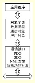
A CANopen device module can be divided into three parts, as shown in Figure 1. The communication interface and protocol software are used to provide services for sending and receiving communication objects on the bus; communication between different CANopen devices is accomplished by exchanging communication objects, and this portion directly faces the CAN controller for operation. The object dictionary describes all the data types, communication objects, and application objects used by the device; the object dictionary is located between the communication program and the application program and provides an interface to the application program. The application operates on the object dictionary to implement CANopen communication. It includes a function part and a communication part. The communication part implements CANopen communication by operating on the object dictionary; and the function part is implemented according to the application requirements.
Figure 1 CANopen device module Each node in the CANopen network system has a unique object dictionary, and each node's object dictionary has the same structure; but the specific content depends on different devices, including description of the device and its network behavior All parameters. The CANopen protocol also defines four kinds of messages (communication objects) for processing information of different roles, namely management messages (NMT), service data objects (SDO), process data objects (PDO) and predefined reports. Text or special function object.
The 2-level telemetering system overall structure liquid level telemetry system mainly realizes 2 functions:
1 Real-time monitoring of the liquid level, temperature and pressure of each cabin;
2 When the monitoring is higher than the alarm value, an alarm signal is issued.
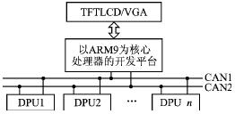
For these two functions, the network topology of the CAN bus is used. The overall system block diagram of the system is shown in Figure 2.
Figure 2 The overall structure of the liquid level telemetry system From Figure 2, we can see that the entire system communicates with the CAN bus. However, the CAN chip only provides the physical layer and link layer functions in the Open System Interconnection Reference Model (OSI). General users must directly use the driver to operate the link layer. Can not directly meet the control network configuration and product interconnection requirements. In order to build a complete industrial control fieldbus system based on the CAN chip, a corresponding application layer protocol must be developed to achieve system configuration, device interconnection, and compatibility functions. The functions of each section are described below.
2.1 Distributed Processing Unit DPU
DPU is an intelligent remote I/O unit with modular design and communication function. The DPU unit is distributed throughout the cabin and serves as an interface between sensors and actuators, directly connected to sensors and actuators. Each DPU unit can be connected to the CAN bus with two ordinary dual-core shielded cables (or twisted pairs, etc.), and various real-time data such as the liquid level and temperature of each cabin that is collected at regular intervals are sent to the bus.
Currently, various modules (analog input/output, digital input/output, etc.) of the DPU based on CANopen can be connected to the network according to specific monitoring points to complete monitoring of liquid level, temperature, and pressure.
2.2 Upper monitoring point In this system, the upper monitoring point mainly implements two functions of communication and application. The specific structure is shown in Figure 3.
Figure 3 upper monitoring point structure The ARM9 development platform has embedded the CAN driver. According to the CAN2.0 protocol, the physical layer and the data link layer can be directly communicated. Therefore, under the WinCE operating system, CANopen communication is achieved, the communication object is resolved, and the application program is called. CANopen communication of the entire upper system.
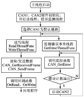
The realization of 3 CANopen communication 3.1 CAN communication CAN communication realizes by calling the interface function of the bottom package, mainly include:
Open port CAN_StartChip;
Off port CAN_StartChip;
Receive CAN data CAN_GetNextReceivedFrame;;
Send CAN data CAN_SendFrame.
The specific communication flow is shown in Figure 4.
Figure 4 CAN communication process 3.2 CANopen Communication The CANopen protocol is the protocol of the CAN communication application layer. Communication standards define different communication objects that are distinguished by identifier (COB_ID).
Network Management Message (NMT): Provides network management services such as initialization, error control, and device status control. The NMT object maps to a single CAN frame with a 2-byte data length with an identifier of 0. In this system is mainly used for system startup initialization.
Process Data Objects (PDOs): Process data objects are used to transfer real-time data, data transfer is limited to 1 to 8 bytes, and each PDO has a unique identifier. The identifier has priority. The telemetry system mainly displays the real-time liquid level and other information, and a large amount of PDO data is transmitted in real time.
Service Data Object (SDO): SDO transmission is a proven service with high reliability. It is mainly used to configure or set information for each node in the system.
The above 4 kinds of objects all have different priorities. The CANopen communication can be realized by parsing the received message according to its COB_ID and distributing different application variables.
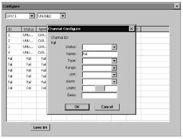
4 Application Module Implementation 4.1 System Configuration This system adopts the configuration file to enhance the flexibility of configuration. The configuration file is a txt file that is based on the field distribution of each module and channel in the lower DPU. First, use a removable disk or RemoteFileViewer to load the configuration file on the PC. Followed by reading the work, through the function GetProfileString, according to different fields to obtain the required content. Finally, the content obtained is assigned to the corresponding variable and the display is updated.
The specific configuration is shown in Figure 5. As can be seen from the figure, you can set the use of the module in the system, cabin name, signal type, unit, range, alarm limit, alarm delay and so on. Therefore, the basic preparation can be completed in the centralized control room, which greatly reduces the burden on the staff.
Figure 5 System Configuration 4.2 Real-time display In order to realize real-time, accurate and vivid display of system operating conditions, text and graphics are used in this module. Because of the large amount of data, more types of interfaces, and frequent switching, the solution to dynamically creating controls has been adopted.
The liquid level telemetry system mainly completes the real-time display of each tank liquid level. In addition, it also includes important information such as the temperature and pressure of the cargo tanks, and the pressure of pipelines.
4.3 Data storage In this system, the data storage mainly completes the storage of alarm data and the monitoring of cabin capacity information, using WinCE's own database system.
The system stores mainly alarm data, so the data volume is relatively small, and using its own database can easily achieve the required functions. In addition, EVC 4.0 does not provide an interface to access the external database ADOCE.
4.4 Real-time printing In this system, real-time printing is realized, that is, as soon as the alarm information appears, the information is printed out; when the fault is eliminated, printing is performed again to save and analyze the data.
5 conclusions This article is based on the CANopen protocol, the ship's liquid level telemetry system software on the ARM9 WinCE embedded development platform. CANopen, as an application layer protocol of CAN bus, has a broad application prospect in ship telemetry system.
The application of CAN bus in the system greatly improves the overall transmission rate of the system. The dual CAN mechanism further enhances the fault-tolerance capability of the entire system and ensures the safety of ship operation. The entire software system implements CANopen communication, completes data display, storage, printing, and alarm, and makes the configuration more intelligent. Experiments have proved the reliability of its operation.
References [1]Cui Xiaojun.Application of new technology in ship's liquid level telemetry system[J].Ship Engineering,2007(3):7274.
[2] Min Kuanming. CAN bus principle and application system design [M]. Beijing: Beijing University of Aeronautics and Astronautics Press, 1996.
[3]Wang Bing, Li Cunbin. Advanced programming of EVC and its application development [M]. Beijing: China Water Power Press, 2005.
[4] Robert Bosch GmbH, CANSpecification Version 2.0 [S], 1991, Postfach 300240, D70442 Stuttgart.
Zhao Weili (Master), the main research direction for communication and measurement and control technology; Wang Zhigang (professor, master tutor), the main research direction for computer measurement and control technology.
Introduction The liquid level telemetry system is the core part of oil tankers and chemical tankers [1], and it is directly related to the safety and reliability of ships sailing at sea. At present, the domestic industry is still in a vicious competition with low technology. To change this situation, it can only be achieved by upgrading the level of technology. The system is designed and researched in this context.
The system is based on ARM9 as the core, in the WinCE operating system platform, based on CAN communication, CANopen protocol as a standard, comprehensive application of EVC programming, CAN communication, database, multi-threading and other technologies designed for a smart liquid level telemetry system.
ARM9's operating frequency is up to 200MHz, microprocessor built-in color image processing circuit, so you can directly external TFTLCD / VGA display.
The CAN (Controller Area Network) bus is a multi-master-slave architecture, with the advantages of message arbitration, error self-detection, processing mechanism, strong communication capability, strong short circuit protection capability, and flexible communication methods. The ship's liquid level telemetry system is a local area network control system. The use of CAN bus can satisfy the high reliability of its transmission [2].
1 CANopen Protocol CANopen was originally developed by CiA members who are engaged in industrial control. Since CANopen is a public, open, and universal protocol, it is also concise, transparent, and easy to develop. Today it has been accepted as one of the standards of CAN high-level protocols. [3]
A CANopen device module can be divided into three parts, as shown in Figure 1. The communication interface and protocol software are used to provide services for sending and receiving communication objects on the bus; communication between different CANopen devices is accomplished by exchanging communication objects, and this portion directly faces the CAN controller for operation. The object dictionary describes all the data types, communication objects, and application objects used by the device; the object dictionary is located between the communication program and the application program and provides an interface to the application program. The application operates on the object dictionary to implement CANopen communication. It includes a function part and a communication part. The communication part implements CANopen communication by operating on the object dictionary; and the function part is implemented according to the application requirements.

Figure 1 CANopen device module
The 2-level telemetering system overall structure liquid level telemetry system mainly realizes 2 functions:
1 Real-time monitoring of the liquid level, temperature and pressure of each cabin;
2 When the monitoring is higher than the alarm value, an alarm signal is issued.
For these two functions, the network topology of the CAN bus is used. The overall system block diagram of the system is shown in Figure 2.

Figure 2 The overall structure of the liquid level telemetry system
2.1 Distributed Processing Unit DPU
DPU is an intelligent remote I/O unit with modular design and communication function. The DPU unit is distributed throughout the cabin and serves as an interface between sensors and actuators, directly connected to sensors and actuators. Each DPU unit can be connected to the CAN bus with two ordinary dual-core shielded cables (or twisted pairs, etc.), and various real-time data such as the liquid level and temperature of each cabin that is collected at regular intervals are sent to the bus.
Currently, various modules (analog input/output, digital input/output, etc.) of the DPU based on CANopen can be connected to the network according to specific monitoring points to complete monitoring of liquid level, temperature, and pressure.
2.2 Upper monitoring point In this system, the upper monitoring point mainly implements two functions of communication and application. The specific structure is shown in Figure 3.

Figure 3 upper monitoring point structure
The realization of 3 CANopen communication 3.1 CAN communication CAN communication realizes by calling the interface function of the bottom package, mainly include:
Open port CAN_StartChip;
Off port CAN_StartChip;
Receive CAN data CAN_GetNextReceivedFrame;;
Send CAN data CAN_SendFrame.
The specific communication flow is shown in Figure 4.

Figure 4 CAN communication process
Network Management Message (NMT): Provides network management services such as initialization, error control, and device status control. The NMT object maps to a single CAN frame with a 2-byte data length with an identifier of 0. In this system is mainly used for system startup initialization.
Process Data Objects (PDOs): Process data objects are used to transfer real-time data, data transfer is limited to 1 to 8 bytes, and each PDO has a unique identifier. The identifier has priority. The telemetry system mainly displays the real-time liquid level and other information, and a large amount of PDO data is transmitted in real time.
Service Data Object (SDO): SDO transmission is a proven service with high reliability. It is mainly used to configure or set information for each node in the system.
The above 4 kinds of objects all have different priorities. The CANopen communication can be realized by parsing the received message according to its COB_ID and distributing different application variables.
4 Application Module Implementation 4.1 System Configuration This system adopts the configuration file to enhance the flexibility of configuration. The configuration file is a txt file that is based on the field distribution of each module and channel in the lower DPU. First, use a removable disk or RemoteFileViewer to load the configuration file on the PC. Followed by reading the work, through the function GetProfileString, according to different fields to obtain the required content. Finally, the content obtained is assigned to the corresponding variable and the display is updated.
The specific configuration is shown in Figure 5. As can be seen from the figure, you can set the use of the module in the system, cabin name, signal type, unit, range, alarm limit, alarm delay and so on. Therefore, the basic preparation can be completed in the centralized control room, which greatly reduces the burden on the staff.

Figure 5 System Configuration
The liquid level telemetry system mainly completes the real-time display of each tank liquid level. In addition, it also includes important information such as the temperature and pressure of the cargo tanks, and the pressure of pipelines.
4.3 Data storage In this system, the data storage mainly completes the storage of alarm data and the monitoring of cabin capacity information, using WinCE's own database system.
The system stores mainly alarm data, so the data volume is relatively small, and using its own database can easily achieve the required functions. In addition, EVC 4.0 does not provide an interface to access the external database ADOCE.
4.4 Real-time printing In this system, real-time printing is realized, that is, as soon as the alarm information appears, the information is printed out; when the fault is eliminated, printing is performed again to save and analyze the data.
5 conclusions This article is based on the CANopen protocol, the ship's liquid level telemetry system software on the ARM9 WinCE embedded development platform. CANopen, as an application layer protocol of CAN bus, has a broad application prospect in ship telemetry system.
The application of CAN bus in the system greatly improves the overall transmission rate of the system. The dual CAN mechanism further enhances the fault-tolerance capability of the entire system and ensures the safety of ship operation. The entire software system implements CANopen communication, completes data display, storage, printing, and alarm, and makes the configuration more intelligent. Experiments have proved the reliability of its operation.
References [1]Cui Xiaojun.Application of new technology in ship's liquid level telemetry system[J].Ship Engineering,2007(3):7274.
[2] Min Kuanming. CAN bus principle and application system design [M]. Beijing: Beijing University of Aeronautics and Astronautics Press, 1996.
[3]Wang Bing, Li Cunbin. Advanced programming of EVC and its application development [M]. Beijing: China Water Power Press, 2005.
[4] Robert Bosch GmbH, CANSpecification Version 2.0 [S], 1991, Postfach 300240, D70442 Stuttgart.
Zhao Weili (Master), the main research direction for communication and measurement and control technology; Wang Zhigang (professor, master tutor), the main research direction for computer measurement and control technology.
Produce by Food Grade PP material, this PP spoon is a good solution for eating various dishes without getting hands involved . Its usability: Airline catering, food courts, hotels, parties, fast food and Ice cream outlets, coffee shops,picnic, outdoor events and all types of catering houses.


Plastic Spoon ,Disposable PP Cutlery,PP Disposable Spoon,Disposable Plastic Cutlery,Disposable Spoon,Reusable Plastic Spoons
BILLION PLASTIC MANUFACTURING CO.,LTD, JIANGMEN , https://www.jmfoodpackagingbag.com