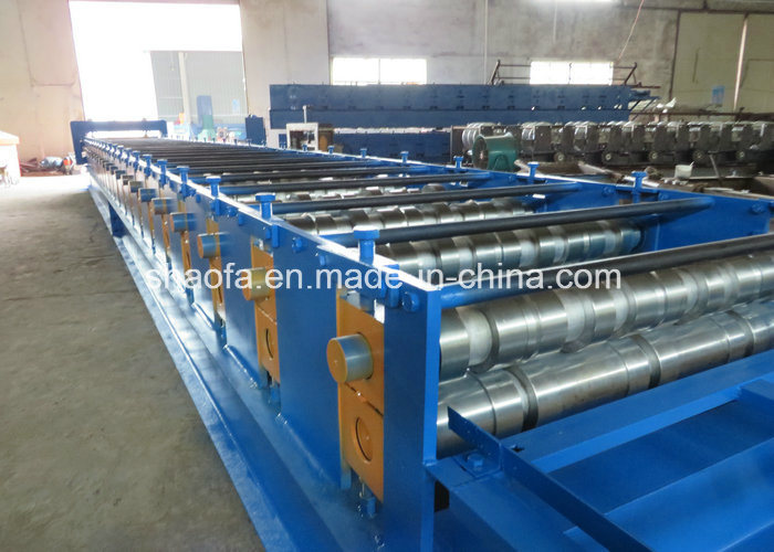
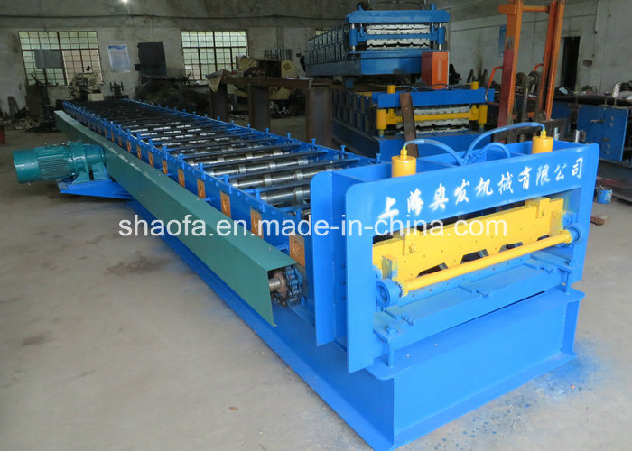
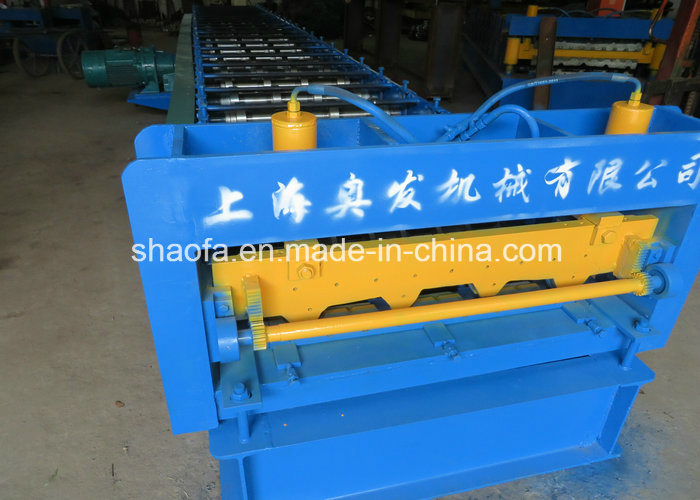
- Model NO.: AF-D1025
- Condition: New
- Usage: Floor
- Type: Concrete Iron Connection Machinery
- Machine Size: 15m*1.6m*1.4m
- Machine Color: as Require
- Cutting Type: Hydraulic
- Size of Container: 40gp
- Trademark: Aofa
- Specification: SGS
- HS Code: 84552210
- Tile Type: Glazed Steel
- Customized: Customized
- Transmission Method: Machinery
- Name: Decking Sheet Roll Forming Machine
- Machine Weight: 7tons
- Control System: PLC
- Driven Type: Chain
- Roller Material: 45#Steel
- Transport Package: Normal
- Origin: Shanghai
Other machine we manufacture
Cold roll forming mahcine, color steel roll forming machine, roof and wall panel machine, decking floor roll forming machine, floor decing forming mahcine, stud and track roll forming machine, ZÂ and CÂ purlin machine, highway guardrail roll forming machine, cable tray machine, and so on.
Working flow:
Decoiler-----feeding------roll forming ------ cutting----output table
Component
| No. | Name | Qty |
| 1. | De-coiler | 1 Set |
| 2. | Feeding and Guiding Device | 1 Set |
| 3. | Roll Forming Machine | 1 Set |
| 4. | Hydraulic Cutting Device | 1 Set |
| 5. | PLC Control Box | 1 Set |
| 6. | Output table | 1 Set |
Techincal description:
A Decoilr                        Â
1 Load Capacity 5T
2Coil Inner-Diameter≤ 508mm
3Coil Outer-Diameter≤ 3000mmÂ
B Roll forming machine
1Feeding material: 1000mm
2Effecvtive material: 688mm
3Material thickness: 1-3mm
4Forming Steps: 30-steps
5Line Speed: 8Â to 15m/min
6Stand: Independent stand structure (raft structure)
7Drive: Independent motor and moved by chain
8Material of Roller: 40Cr, HRC45-55
9Shaft Diameter: 100mm
10Main Motor Power: About 80KW
11Shaft of material45#steel after treatment
12Voltage: 380V/50Hz/Three Phase
C Cutting device
1Cutting Die: Cr12, HRC58-62
2Tolerance: ± 2mm
3Valve: Adopts Italy Atos
D Control system
Type: PLC Frequency Control System with touch screen
PLC Brand: Japan Panasonic
Encoder Brand: Omron
Length Error: ± 2mm
Transducer: Panasonic
E Output table
1Function: It is simple and used to load finished product.
2Length: 6m
Service
| Terms | Â |
| Payment  type | 35%  T/T  prepaid  and  balance  should  be  paid  before  loading |
| Delivery  time | 45days after receving advance payment. |
| Guarantee  period | 18monthes  free  service/  pay  service  all  the  machine  life |
| Installation  and  training  |
If  buyers  visit  our  factory  and  check  the  machine, we  will  teach  you  how  to  install  and  use  the  machine, and  also  train  your  workers/technician  face  to  face. Without  visiting, we  will  send  you  user  manual and  video  to  teach  you  to  install  and  operate. If  buyer  needs  our  technician  to  go  to  your  local  factory, please  arrange  board  and  lodging  and  other  necessary  things. |
Contact:
Abby Song
Â
Â


The clamp with earth cable is used to make the electrical connection between the power source and the base material to be welded. The section and length of the cable are determined by the maximum current from the power source.
What does Grounding have to do with Arc Welding Safety
?
Grounding of electrical circuits is a safety practice that is documented in various codes and standards. A typical arc welding setup may consist of several electrical circuits. Applying and maintaining proper grounding methods within the welding area is important to promote electrical safety in the workplace. Associated processes such as plasma cutting will also benefit from proper grounding. The important grounding topics in a typical welding environment are discussed.
Grounding and Arc Welding Safety
Welding Machine Ground
Welding Machines that utilize a flexible cord and plug arrangement or those that are permanently wired into an electrical supply system contain a grounding conductor. The grounding conductor connects the metal enclosure of the welding machine to ground. If we could trace the grounding wire back through the electrical power distribution system we would find that it is connected to earth, and usually through a metal rod driven into the earth.
Grounding and Arc Welding Safety
The purpose of connecting the equipment enclosure to ground is to ensure that the metal enclosure of the welding machine and ground is at the same potential. When they are at the same potential, a person will not experience an electrical shock when touching the two points. Grounding the enclosure also limits the voltage on the enclosure in the event that insulation should fail within the equipment.
The current carrying capability of the grounding conductor is coordinated with the overcurrent device of the electrical supply system. The coordination of ampacity allows the grounding conductor to remain intact even if there is an electrical fault within the welding machine.
Some welding machines may have a double insulated design. In this case, a grounding conductor connection is not required. This type of welding machine relies on extra insulation to protect the user from shock. When double insulation is present it is identified by a "box within a box" symbol on the rating plate.
Grounding and Arc Welding Safety
For small welding machines that utilize a plug on the end of a power cord, the grounding conductor connection is made automatically when the welding machine is plugged into the receptacle. The grounding pin of the plug makes a connection within the receptacle. The use of adapters that effectively remove the grounding pin connection at the plug is not recommended. Furthermore, do not cut off or remove the grounding pin from the plug. All safety benefit of the grounding conductor is lost without the connection.
Grounding and Arc Welding Safety
Receptacle circuit testers will easily check the continuity of the grounding conductor. Receptacle circuit testers for 120-volt circuits are available at electrical supply or hardware stores; these inexpensive test devices plug into an electrical outlet. Indicator lights show whether the grounding circuit is available at the outlet, as well as other circuit tests. If the test device shows the absence of a ground connection or other circuit problem, call a qualified electrician for assistance. This is a simple test and should be done periodically. Consult with a qualified electrician to test circuits greater than 120 volts.
Grounding and Arc Welding Safety
Workpiece Ground
The welding circuit consists of all conductive material through which the welding current is intended to flow. Welding current flows through the welding machine terminals, welding cables, workpiece connection, gun, torch, Electrode Holder and workpiece. The welding circuit is not connected to ground within the welding machine, but is isolated from ground. How do we ground the welding circuit?
According to ANSI Z49.1, "Safety in Welding, Cutting and Allied Processes," the workpiece or the metal table that the workpiece rests upon must be grounded. We must connect the workpiece or work table to a suitable ground, such as a metal building frame. The ground connection should be independent or separate from the welding circuit connection.
Grounding and Arc Welding Safety
Grounding the workpiece has similar benefit to grounding the welding machine enclosure. When the workpiece is grounded, it is at the same potential as other grounded objects in the area. In the event of insulation failure in the arc welding machine or other equipment, the voltage between the workpiece and ground will be limited. Note that it is possible to have an ungrounded workpiece, but this requires the approval of a qualified person.
The Workpiece Connection is not a Ground Clamp
"Ground clamp" and "ground lead" are common terms used by many welders. The workpiece is connected to a welding cable typically by means of a spring loaded clamp or screw clamp. Unfortunately, a workpiece connection is often incorrectly called a "ground clamp" by many welders and the workpiece lead is incorrectly called "ground lead." The welding cable does not bring a ground connection to the workpiece. The ground connection is separate from the workpiece connection.
High Frequency Ground
Some welding machines utilize starting and stabilizing circuits that contain a high frequency voltage. This is common on Tungsten Inert Gas (TIG) welding machines. The high frequency voltage may have frequency components that extend into the megahertz region. In contrast, the welding voltage may be as low as 60 Hertz.
High frequency signals have a tendency to radiate away from the welding area. These signals may cause interference with nearby radio and television reception or other electrical equipment. One method to minimize the radiation of high frequency signals is to ground the welding circuit. The welding machine instruction manual will have specific instructions on how to ground the welding circuit and components in the surrounding area to minimize the radiation effect.
Portable and Vehicle Mounted Welding Generator Grounding
Portable and vehicle mounted arc welding generators often have the capability to supply 120 and 240 volt auxiliary power. These generators are used in remote locations away from an electrical power distribution system. A convenient earth ground is not usually available for connection. Should the generator frame be grounded?
The rules for grounding depend on the specific use and design of the auxiliary power generator. Most applications fall into one of the two categories summarized below:
1. If all of these requirements are met, then it is not required to ground the generator frame:
The generator is mounted to truck or trailer
The auxiliary power is taken from receptacles on the generator using a cord and plug arrangement
The receptacles have a grounding pin
The frame of the generator is bonded, or electrically connected, to the truck or trailer frame
2. If either of these conditions are met, then the generator frame must be grounded:
The generator is connected to a premises wiring system. For example, to supply power to a house during a blackout.
The auxiliary power is hard wired into the generator without the use of cords and plugs.
The summary above does not go into details and the reader is urged to consult their local electrical codes and ANSI/NFPA 70, "National Electrical Code" for the specifics.
Extension Cord Grounds
Extension cords should be periodically tested for ground continuity. Extension cords lead a rough life while lying on the ground; they are under foot and prone to damage. The use of a receptacle circuit tester will confirm that all of the connections are intact within the cord, plug and receptacle.
Welding Circuit Shock Hazards
Utilizing proper grounding in the welding environment is a good practice, but it does not remove all possibility of electrical shock. The welding circuit is energized by welding voltage. A person will receive a shock if they become the electrical path across the welding circuit. Precautions must be taken to insulate the welder from the welding circuit. Use dry insulating gloves and other insulating means. Also maintain insulation on weld cables, electrode holders, guns and torches to provide protection.
Similarly, electric shock originating from the electrical supply system can be prevented. Proper maintenance of electrical equipment and extension cords will insulate the welder from electrical sources.
Information Sources
American Welding Society, ANSI Z49.1:2005 "Safety in Welding, Cutting, and Allied Processes."

National Fire Protection Association, NFPA 70, "National Electrical Code", 2005.

American Welding Society, Safety and Health Fact Sheet No. 29, "Grounding of Portable and Vehicle Mounted Welding Generators", July 2004.

American Welding Society, AWS A3.0-2001, "Standard Welding Terms and Definitions."
Earth Clamp,Copper Earth Clamp,Copper Grounding Clamp,Brass Clamp For Earth
Changzhou Edaweld Trading Company Limited , https://www.edaweld.com