There are basically two kinds of heap leaching: 1 raw ore heap leaching: there are two cases in the original ore heap leaching. One is to treat those underground or open pit mines with low grade and can not be treated by traditional techniques. In the case of direct immersion on a pre-made dip pad. The other is for direct in-situ leaching of tailings piles or ore piles with very low grades, often referred to as original heap leaching. The ore leaching period is long, often takes months or even years, the particle size is about -152mm, and it can also contain some large boulders. 2 heap leaching of ore after crushing: usually the ore is broken to -19mm, and sometimes it can be broken to about 6.0mm. The crushed ore is then transported to a pre-made dip pad for leaching. This leaching method is characterized by a short cycle, from a few weeks to a few months.
The broad heap leaching, can be divided into three categories: the first is the most common heap leaching, the ore mined crushed to the required size, heap construction, leaching leaching, an immersion gold; Second pit heap leaching, the ore placed in the pit leaching, common copper ore and uranium leaching; Third, underground leaching, this method is economical, safe, less investment, but there are immersion leakage problem. In North America, production by these three methods accounted for 73%, 23% and 4% respectively. The heaping amount is 5×10 4 t, accounting for 50%, 5×10 4 to 10×10 4 t, accounting for 17%, and 10×10 4 to 30×10 4 t, accounting for 6-11%, with 17%. More than 30 × 10 4 t.
1. Overall layout of the heap leaching field
The topography and location of the leaching site significantly affect the final design, infrastructure investment and production costs of the heap leaching operation. At the same time, the size and type of the site and the way the solution is transported are closely related to the ground and height used. Therefore, the following design factors should be considered when determining the base of the heap immersion field:
1 Close to the mine source: The closer the site is to the mine source, the lower the transportation cost.
2 Close to the water source: The heap leaching process is a wet process, and water is an essential material guarantee in production; reliable and ideal water supply conditions are not only convenient for production, but also reduce production costs.
Poor status: The ideal field position can reduce infrastructure investment and production costs, and can effectively extend the service life of the venue. Figure 1 not only reflects the difference in the heap leaching field, but also reflects the ideal design factors.
 [next]
4 Convenient traffic conditions and power supply conditions are also important factors that cannot be ignored in the design.
2. Diffuse pad
In order to collect the precious liquid, an impervious dipping mat is needed, so as to avoid the loss of the gold-containing cyanide liquid into the ground, and also eliminate the pollution of rivers and groundwater. To this end, a dip mat must be constructed to allow the solution to seep through the heap to the dip pad and collect in the central drain to flow to the first solution cell. The dip mat must be constructed on a solid floor with two or three reservoirs located near one end of the dip pad. These three reservoirs are the noble, the lean and the overflow. Materials for impervious dip mats include: 1 plastic or rubber film laid on a flat and slightly sloping floor, covered with a layer of washed sand or small gravel; 2 compacted tailings mixed with sticky; 3 asphalt Spread on compacted gravel and covered with a layer of asphalt protective layer; 4 reinforced concrete; 5 clay .
1) Steps for building a mat 1 Select a solid place on the ground as a heap leaching field; 2 Fill the pile leaching site with soil to form a slope; 3 Level the floor with a roller and compact the dipping mat as much as possible. At the end of the dip pad, a 30~90cm deep underground drainage ditch is set every 30m; 4 at the end of the dipping pad, a drainage ditch and three liquid storage tanks are arranged. The length, width and height of each pool are 12m, 6m and 3m respectively. The first reservoir (precious tank) is located on one side of the existing drain, 3m away from the mine. The second reservoir (lean pool) is about 3m away from the first pool, and the third pool (overflow pond) is about 3m away from the second pool; 5 is covered with 10~15cm thick fine sand and small gravel The surface of the dip pad and the bottom of the reservoir. This prevents the plastic film from being perforated; 6 the bottom surface of the dip pad is engraved with a diagonal line to prepare a passage for the solution to flow to the drain groove next to the dip pad. Use a 45kg hammer to tamper and double the bottom of the dip pad; 7 build a 60cm high plane around the entire heap immersion field; 8 Once the heap immersion field is really compacted, cover it with a 0.8mm thick Hepalon plastic film. it is good. Through a plastic film, a drain pipe is connected to the precious liquid pool; 9 is covered with a 0.8mm thick plastic cloth on the bottom surface and the side of the three liquid storage tanks; 10 is covered with 10~15cm thick sand covered with plastic cloth The pile of dip tables. This prevents large pieces of angular ore piled up on the plastic sheet from puncturing the plastic sheet; (11) due to the use of cyanide, the entire spray area is restricted from entering and exiting, and warning signs are placed around the mine yard and all reservoirs.
2) Dip Pad Types Several dip pad systems are currently in use, and several are also recommended for use. Each pad system is designed to meet specific engineering needs, economic material constraints, or environmental protection. Requirements. Many of the liner materials in the project have a low contact surface shear strength that controls the stability of the heap.
The heap immersion liner material can be clay, modified soil, concrete, asphalt or polymeric films (eg, polyvinyl chloride, high density polyethylene). Some liners are often used in combination to provide a wear resistant surface and redundancy. Figure 2 shows the various liner systems currently in use. [next]

1 single layer liner. The single layer liner can be laid directly onto the prepared foundation or sand cushion. When clay, modified soil, concrete or asphalt is used, its strength is so high that both the liner and the base material control the stability of the heap. When a polymer film is used, especially when it is placed next to a fine-grained foundation, the Frictional Content Strength is very low and usually controls the stability of the heap. Ground fabrics used as a protective layer, a mat or a drainage layer above the film can also produce very low frictional contact strength.
2 double padding. The top liner of the double liner system is typically in contact with the working solution, while the underlying liner is used as a supplement to prevent solution from leaking into the environment. The two layers of pads can be in direct contact with one another or form a drainage layer between them. The drainage layer is effective for detecting leaks and is also used to collect and recover leaching solutions. For a lower heap, a thick layer of fabric can be used as a drainage layer between layers. However, when the pile is relatively high, a layer of granular drainage is required. Geonets can be used under low and medium stress conditions.
When using double-layer liners, special care must be taken to ensure the frictional strength of the contact between different materials. Contact between the mulch and the ground fabric, the ground mesh or the clay liner can produce relatively low strength. A particulate drainage layer and a cushion layer (Cushion-inglayey) provide the best way to maintain a contact strength that is almost equal to the strength of the material itself.
3 three-layer pad. Three-layer liners are uncommon and are only used in the downstream areas due to environmental impact problems due to leakage of leaching solution and near high-risk areas of historically active faults. There is at least one, possibly two, drainage layers between each of the liner layers of the three-layer liner system. When the drainage capacity is large enough, the lowest layer of liner can be considered as "Zero Head Liner" in the Hazadous Waste Industry. The strength problem of the three-layer liner system can be solved in the same way as the double liner system.
3. Pile up
The dip is built in a flat zone, inclined 1% laterally to one side and 3% to 4% longitudinally. In this way, the noble liquid can be led to the corner of the immersion pile, and the lining discharge groove is fed into the corner, and finally flows into the noble liquid pool. [next]
The heap leaching ore can be in the range of 0.5×10 4 ~200×10 4 t, and the weight of each heap of ore is not standardized. Depending on the specific situation, the weight of a dip in a mine in the United States is as high as 1×10 8 t. The stack height depends on factors such as permeability, cyanide concentration and oxygen content. The dissolved oxygen must remain in the heap leaching solution and it is percolated until it reaches the bottom of the heap. When the heap is too high or too thick, the dissolved oxygen is consumed when the solution has not penetrated to a lower point. In addition, the height of the pile is usually related to the maximum height reached before the loader bucket.
In order to load the crushed ore into the mine, it is recommended to use a tire loader or a dump truck. Building in this way maintains the uniformity of the material. However, material segregation may occur when a belt conveyor is used to build the pile. The fine particles tend to concentrate in the center of the heap, and the coarse materials are concentrated at the slope and at the bottom of the heap. When a belt conveyor is used to build a pile, the leachate tends to be restricted to a place with good gas permeability (ie, a coarse material), so that it is impossible for the solution to pass through the poorly permeable material (ie, at the fine material).
After the broken ore is piled up, the heap should be flat. Large ore piles should be flattened with a bulldozer with coarse teeth, and small ore piles can usually be flattened with concrete or concrete.
The mine site should be provided with a non-permeable layer, that is, a sealed dipping mat, to prevent the cyanide liquid from infiltrating the soil under the pile. If a heavy-duty transport vehicle is designed to work on the top of the pile, asphalt is used as the basis. If a plastic film is used as the anti-seepage layer, a layer of buffer sand should be laid under the film. Otherwise, the plastic film will be cut at the time of pile-up, and the wet clay and tailings can also be used as a dip pad. A layer of sand or gravel is placed on the mat to provide a passage for the flow of the noble liquid. The Yangu Mining Company uses the crushing plant to provide a large ore for the bottom cover. The dump truck transports the ore to the heap leaching site and mines it with bulldozers, rake mining machines and front end loaders. Bulldozers are the most commonly used ore equipment, but many mines use transporters and stackers. Transporters and stackers are used to avoid heavy equipment being piled up during stacking.
Currently, the immersion capacity has not been standardized. However, 50% of the heaps in the North American heap leaching plant are under 5×10 4 t, 17% are 5×10 4 ~10×10 4 t, and 17% are more than 30×10. 4 t, the remaining heap is 10 × 10 4 ~ 30 × 10 4 t. The following are some common methods of building piles:
1) Multi-stack method This method uses a belt conveyor to pile the ore into a number of piles with a certain height (see Figure 3).
 [next]
It can be seen from the figure that the coarse ore is rolled to the edge of the pile, and the fine ore is in the pile, and the two ores form the respective size regions. When the bulldozer flattens the top of the pile, the top of the pile is compacted. Thus, the immersion liquid does not flow through the coarse area immediately after flowing through the pile, so that the immersion liquid cannot penetrate the entire pile evenly and leaching. The effect is also correspondingly poor (see Figure 4).

2) Multi-layer method In the multi-layer pile method (Fig. 5), each layer of ore in the pile is about 1.5-3 m thick. In the current production, each layer of ore is 1-7 m thick. After the first layer of ore is immersed, it can be transported away from the dip pad, or a second layer of ore can be continuously laid on it, so that the immersion liquid can leach out two layers of ore. The third and fourth layers of ore can then be laid. If the treated ore is finer in size, usually only one layer of ore is laid, because after the leaching is completed, the ore is substantially free of useful components, which can be transported away from the dip pad and discarded. Conversely, for a large-sized ore, a longer leaching time is required, and a multi-layer pile-up method is employed to allow the remaining useful components in the lower layer to be leached without wasting the useful space of the dip pad.

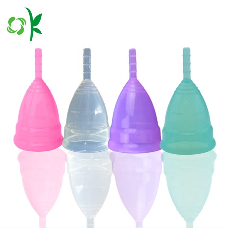
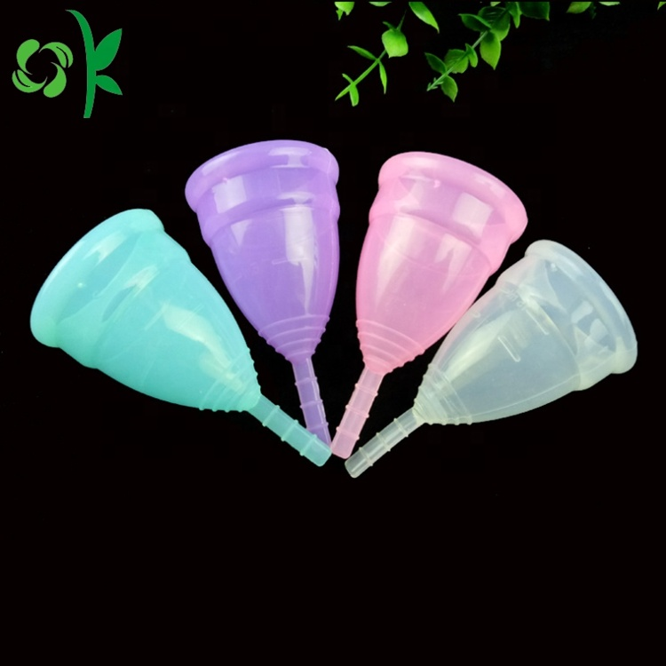
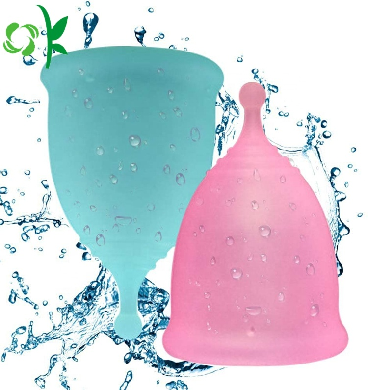
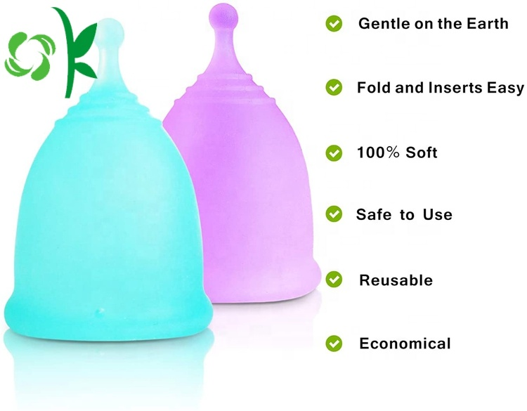
This silicone menstrual cup is made for women. It is made of high-quality, safe and harmless materials, which is very comfortable and convenient to use. It is more environmentally friendly than traditional sanitary napkins. Because its structure is very consistent with the structure of the human body, it can avoid the embarrassing situation of side leakage. It also has very high comfort, and there is no foreign body sensation when in use.
Our company's main business includes Silicone Phone Accessories, Silicone Bracelets, Silicone Watchband, Silicone Keychains and Silicone Kitchenware. OK Silicone Gift Co., Ltd, has been focusing on producing high-quality silicone products for many years, we welcome new and old customers to come and have a cooperation!


Wholesale Medical Silicone Menstrual Cup,menstrual cup silicone wholesale,Menstrual cup silicone custom,Custom Medical Silicone Menstrual Cup
Dongguan OK Silicone Gift Co., Ltd. , https://www.dgsiliconebabyproducts.com